
Basic Terminology And Size Calculation Of Gears
Gears have a lot of unique terms and expressions of gears. In order to enable everyone to understand gears more, here are some basic gear terms that are often used.
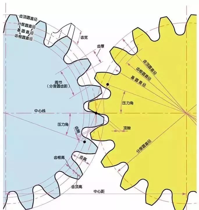
1) The name of each part of the gear
2) The term for the size of gear teeth is modulus
m1, m3, m8… are called modulus 1, modulus 3, and modulus 8. Modulus is a universal name in the world. The symbols m (modulus) and numbers (mm>) are used to indicate the size of the gear teeth. The larger the number, the larger the gear teeth.
In addition, in countries that use imperial units (such as the United States), symbols (diameter pitches) and numbers (number of gear teeth when the pitch circle diameter is 1 inch) are used to indicate the size of the gear teeth. For example: DP24, DP8, etc. There are also special addressing methods that use symbols (circle section) and numbers (mm) to indicate the size of gear teeth, such as CP5 and CP10.
Multiply the modulus by the circumference ratio to get the tooth pitch (p), which is the length between two adjacent teeth. The formula is:
p=circumference ratio x modulus = πm
Comparison of tooth sizes with different modules:
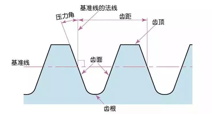
3) Pressure angle
The pressure angle is a parameter that determines the gear tooth profile. That is, the inclination of the gear tooth surface. The pressure angle (α) is generally 20°. In the past, gears with a pressure angle of 14.5° were popular.
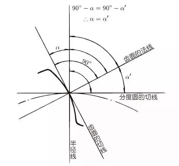
The pressure angle is the angle between the radius line and the tangent of the tooth profile at a point (usually a node) on the tooth surface. As shown in the figure, α is the pressure angle. Because α’=α, α’is also the pressure angle.
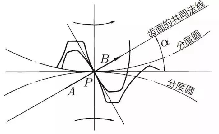
When the meshing state of tooth A and tooth B looks from the node:
Tooth A pushes point B on the node. The driving force at this time acts on the common normal of tooth A and tooth B. In other words, the common normal is the direction of force and the direction of pressure, and α is the pressure angle.
Modulus (m), pressure angle (α) plus the number of teeth (z) are the three basic parameters of the gear. The size of each part of the gear is calculated based on this parameter.
4) Tooth height and tooth thickness
The height of the gear teeth is determined by the modulus (m).
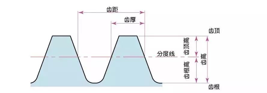
Total tooth height h=2.25m (=tooth root height+tooth top height)
The tooth tip height (ha) is the height from the tooth tip to the index line. ha=1m.
Tooth root height (hf) is the height from the tooth root to the index line. hf=1.25m.
The basis of tooth thickness (s) is half of the tooth pitch. s=πm/2.
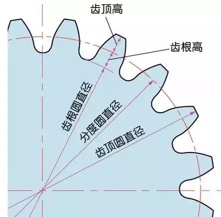
5) The diameter of the gear
The parameter that determines the size of the gear is the index circle diameter (d) of the gear. The pitch, tooth thickness, tooth height, tooth tip height, and tooth root height can be determined based on the index circle.
Diameter of index circle d=zm
Addendum circle diameter da=d+2m
Tooth root circle diameter df=d-2.5m
The index circle cannot be seen directly in the actual gear, because the index circle is a circle assumed to determine the size of the gear.
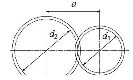
6) Center distance and backlash
When the index circles of a pair of gears mesh tangentially, the center distance is half of the sum of the diameters of the two index circles.
Center distance a=(d1+d2)/2
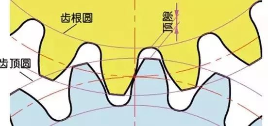
In the meshing of gears, backlash is an important factor in order to obtain a smooth meshing effect. Backlash is the gap between the tooth surfaces when a pair of gears mesh.
There is also a gap in the tooth height direction of the gear. This gap is called Clearance. The head clearance (c) is the difference between the tooth root height of the gear and the addendum height of the matching gear.
Head clearance c=1.25m-1m=0.25m
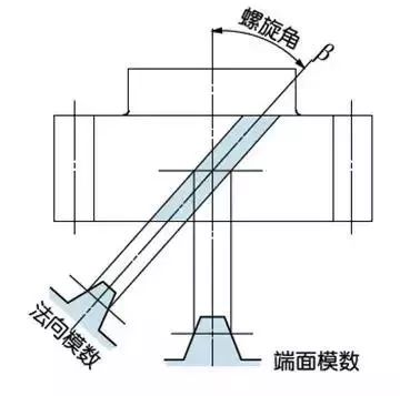
7) Helical gear
A helical gear is a helical gear after the teeth of the spur gear are twisted in a spiral shape. Most of the geometry of spur gears can be applied to helical gears. There are two ways for helical gears according to their reference planes:
End face (shaft right angle) datum (end face modulus/pressure angle>
Normal surface (tooth right angle) datum (normal modulus/pressure angle>
The relationship between the end face modulus mt and the normal modulus mn mt=mn/cosβ
8) Spiral direction and fit
Helical gears, spiral bevel gears, etc., gears with helical teeth, the spiral direction and coordination are fixed. The spiral direction means that when the central axis of the gear points up and down, when viewed from the front, the direction of the gear teeth points to the upper right is [right rotation], and the upper left is [left rotation].