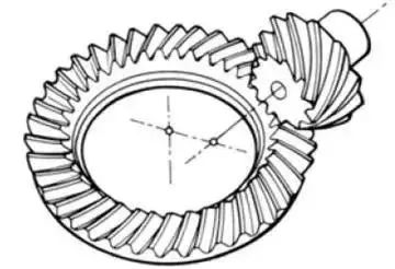
Gear Introduction And Classification
Gear machining is a complex process, and every part of the production process must also reach extremely precise dimensions. The gear processing cycle includes ordinary turning → hobbing → gear shaping → shaving → hard turning → gear grinding → honing → drilling → inner hole grinding → welding → measurement
1. What is a gear?
Gears are toothed mechanical parts that can mesh with each other. It is extremely widely used in mechanical transmission and the entire mechanical field.
2. Gears are generally divided into three categories
There are many types of gears, and the most common classification method is based on the gear axis. Generally divided into three types: parallel axis, intersecting axis and staggered axis.
1) Parallel shaft gears: including spur gears, helical gears, internal gears, racks and helical racks, etc.
2) Intersecting shaft gears: straight bevel gears, spiral bevel gears, zero-degree bevel gears, etc.
3) Cross-axis gears: There are cross-axis helical gears, worm gears, hypoid gears, etc.
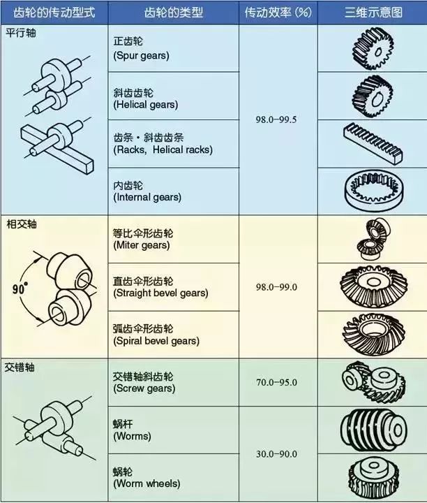
2.1 Gears with parallel shafts
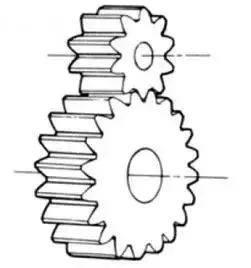
1) Spur gear
The tooth line and the axis line are cylindrical gears in parallel directions. Because it is easy to process, it is the most widely used in power transmission.
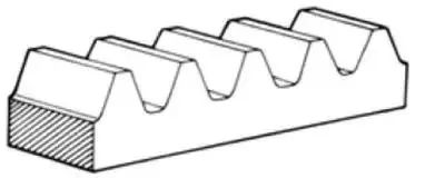
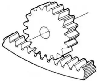
2) Rack
A linear rack gear that meshes with a spur gear. It can be regarded as a special case when the pitch circle diameter of the spur gear becomes infinite.
3) Internal gear
A gear that meshes with a spur gear and has gear teeth machined on the inner side of the ring. Mainly used in applications such as planetary gear transmissions and gear couplings.
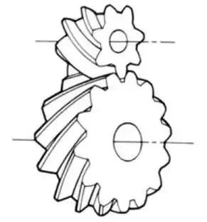
4) Helical gear
The tooth line is a cylindrical gear with a spiral line. Because it is stronger than spur gears and runs smoothly, it is widely used. Axial thrust is generated during transmission.
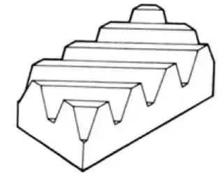
5) Helical rack
A pinion gear that meshes with a helical gear. This is equivalent to the situation when the pitch diameter of the helical gear becomes infinite.
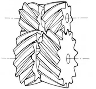
6) Herringbone gear
The tooth line is a gear composed of two helical gears with left-handed and right-handed rotation. It has the advantage of not generating thrust in the axial direction.
2.2 Intersecting shaft gears
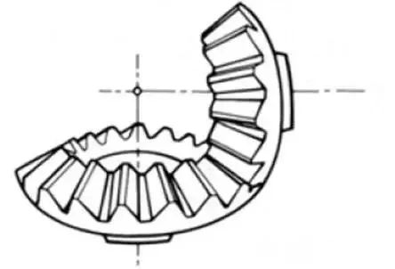
1) Straight bevel gear
A bevel gear whose tooth line is the same as the generatrix of the pitch cone line. Among bevel gears, they are relatively easy to manufacture. Therefore, it has a wide range of applications as a bevel gear for transmission.
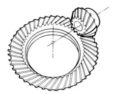
2) Spiral bevel gear
The tooth line is a curved bevel gear with a helix angle. Although it is more difficult to manufacture than straight bevel gears, it is also widely used as a high-strength, low-noise gear.
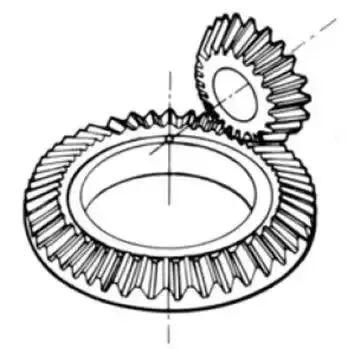
3) Zerol bevel gear
Curved bevel gears with a helix angle of zero degrees. Because it has the characteristics of both straight and curved bevel gears, the force on the tooth surface is the same as that of a straight bevel gear.
2.3 Cross-shaft gears
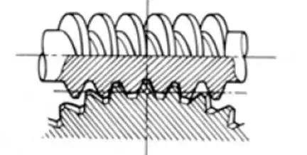
1) Cylindrical worm pair
Cylindrical worm pair is a general term for cylindrical worm and worm gear meshing with it. Quiet operation and a single pair can obtain a large transmission ratio as its biggest feature, but it has the disadvantage of low efficiency.
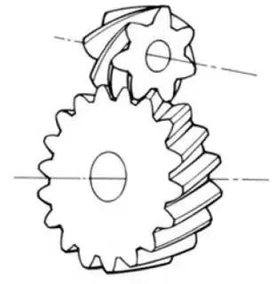
2) Cross-axis helical gears
The name of the cylindrical worm pair when it is transmitted between crossed shafts. It can be used in the case of a helical gear pair or a helical gear and a spur gear pair. Although it runs smoothly, it is only suitable for use under light load conditions.
2.4 Other special gears
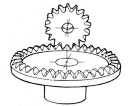
1) Face gear
A disc-shaped gear that can mesh with a spur gear or a helical gear. Transmission between right-angle shaft and cross shaft.
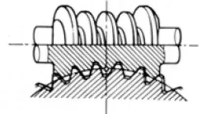
2) Drum worm pair
The general term for drum worms and worm gears that mesh with them. Although it is more difficult to manufacture, it can transmit large loads compared to cylindrical worm gears.
3) Hypoid gear
Conical gears that drive between crossed shafts. Large and small gears are processed eccentrically, similar to spiral tooth gears, and the meshing principle is very complicated.
